OpenStack Home Lab Part 3: Switcheroo
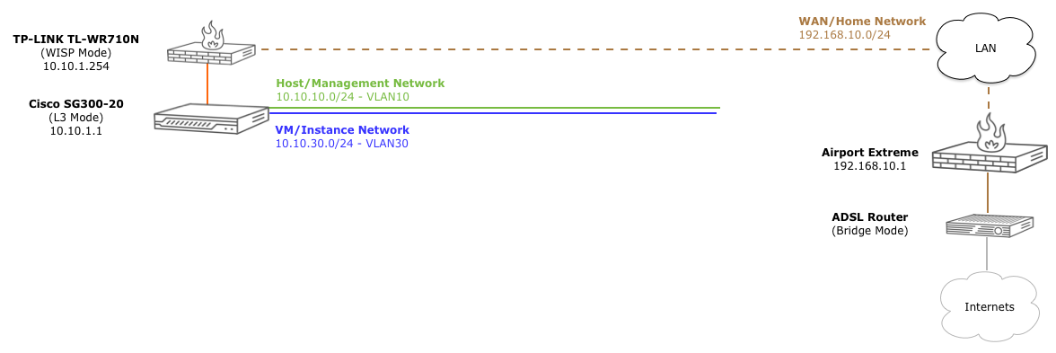
In the last post, we configured our Wireless AP to connect to the existing network and expose a new LAN for the lab. Now it’s time to start configuring our switch to get the proper time, use the new lan network address space, hand out addresses and route to the WAP gateway to the internets.
Dans Courses
Disclaimer: I don’t know jack about switches/routers/vlans…well, I didn’t. I can not praise this youtube channel enough for being a huge resource for getting your mind into working with Cisco-ish hardware. After watching those CCNA videos for a few weeks, I at least had half a chance to understand what I was doing.
Connecting to the switch
While this switch has a pretty awesome GUI interface to configure various, the main goal is to learn a lot of things at once, I’m going to force myself to use the CLI. While this switch is not a Cisco IOS based switch, the cli that is provided is VERY close to IOS.
And to heighten the old school experience, I’m going to use the serial console port and a usb-serial converter to do the configuration. This is handy across switch reboots and ip address changes as the terminal will never get disconnected.

Assuming you have all the cables connected, the switch powered on, and you have a compatible adapter, you should now have a new tty device for this serial connection. Most of the compatible adapters use the “PL2303” chipset, so they usually look something like this:
→ ls /dev/*PL*
crw-rw-rw-  1 root  wheel   18,   5 Apr 30 16:19 /dev/cu.PL2303-000013FD
crw-rw-rw-  1 root  wheel   18,   4 Apr 30 16:19 /dev/tty.PL2303-000013FD
Once you find the right device, we can use screen to connect to the switch, passing it the device, baud rate, bits, parity, and stop bit. Hit <CR> twice to kick off the auto detect, and use the default username/password (cisco/cisco)
→ screen /dev/tty.PL2303-000012FD 115200 8N1

<CR><CR>
Detected speed: 115200

User Name:cisco
Password:*****

Please change your password from the default settings. Please change the password for better protection of your network.
Do you want to change the password (Y/N)[Y] ? N
Don’t bother changing the password. After we change the switch to L3 mode, it will reset all settings, including the existing password.
L3 Mode
By default, the SG300 series of switches are configured to operate in L2 [Switch] mode. In order to do InterVLAN routing, we need to change to L3 [router] mode.
switch162274#show system mode

Feature                 State
-------------------     ---------
Mode:                   Switch

switch162274#set ?
  interface            Interface parameters
  system               Set System features

switch162274#set system ?
  mode                 Ip Routing support

switch162274#set system mode ?
  router               System will run as a IP router
  switch               System will run as a switch

switch162274#set system mode router

Changing the switch working mode will *delete* the startup configuration file
and reset the device right after that. It is highly recommended that you will
backup it before changing the mode, continue ? (Y/N)[N] Y
This is not meant to be an IOS[ish] primer, but if this is your first time, ? will cause inline help to be displayed for the partial command. Tab completion is also available.
At this point, the switch will reset itself into L3 mode, reboot, and reset all existing settings back to factory defaults; all scrolling by at the speed of mud in your console terminal. Once it’s done, we’ll log in again, change our password this time, and double check our mode:
<CR><CR>
Detected speed: 115200

User Name:cisco
Password:*****

Please change your password from the default settings. Please change the password for better protection of your network. Do you want to change the password (Y/N)[Y] ? Y
Enter old password  : *****
Enter new password  : ***********
Confirm new password: ***********


switch162274#show system mode

Feature                 State
-------------------     ---------
Mode:                   Router
Ok, game on. Now for some mundane, but important configuration.
Change the Hostname
Let’s give our switch a hostname because switch162274 isn’t terribly helpful:
switch162274#config terminal

switch162274(config)#hostname ?
  WORD                 This system's network name

switch162274(config)#hostname SG300-20

SG300-20(config)#exit

SG300-20#copy running-config startup-config
Overwrite file [startup-config].... (Y/N)[N] ?Y
12-Jan-2014 18:06:05 %COPY-I-FILECPY: Files Copy - source URL running-config destination URL flash://startup-config
12-Jan-2014 18:06:08 %COPY-N-TRAP: The copy operation was completed successfully
Copy succeeded
After each major change, we’ll get into a habit of copying our running configuration to our startup configured, so our changes are saved and loaded the next time the switch reboots.
VLAN1/Native VLAN Addressing
First, let’s get this thing on the same network as the WAP access point (10.10.1.0/24). As we see below, the default out of the box is 192.168.1.0/24 with dhcp client enabled:
SG300-20#show ip ?
  arp                  ARP information
  dhcp                 IP DHCP information
  helper-address       UDP relay information
  http                 HTTP configuration
  https                HTTPS configuration
  igmp                 IGMP information
  interface            IP interface status and configuration
  route                Display the IP routing table
  source-guard         Show IP Source Guard status
  ssh                  Display the configuration of the SSH server component
  ssh-client           secure shell client.

SG300-20#show ip interface


    IP Address         I/F      I/F Status      Type     Directed   Precedence   Status
                                admin/oper               Broadcast
------------------- ---------- ------------- ----------- ---------- ---------- -----------
0.0.0.0/32          vlan 1     UP/UP         DHCP        disable    No         Not received
192.168.1.254/24    vlan 1     UP/UP         Default     disable    No         Valid
To do that, we simply need to change the ip address interface for vlan 1 (“native” vlan):
SG300-20#config t
SG300-20(config)#interface vlan 1
SG300-20(config-if)#?
  bridge               Bridge configuration commands
  do                   execute an EXEC-level command
  dot1x                dot1x protocol
  end                  Exit from configure mode
  exit                 Exit from current context
  help                 Description of the interactive help system
  ip                   Global IP configuration commands
  ipv6                 IPv6 commands
  name                 set vlan name
  no                   Negate command
  service-acl          Apply an ACL to particular interface.
  shutdown             Shutdown the selected interface
  snmp                 SNMP
  sntp                 Global Simple Network Time Protocol (SNTP)
                       configuration subcommands
SG300-20(config-if)#ip ?
  address              Set the IP address of an interface
  dhcp                 Configure DHCP services
  igmp                 IGMP interface commands
  proxy-arp            Enable proxy ARP on interface
SG300-20(config-if)#ip address ?
  dhcp                 Acquire IP address from DHCP server
  A.B.C.D              IP address
SG300-20(config-if)#ip address 10.10.1.1 ?
  A.B.C.D or /n        IP subnet mask or IP prefix length
SG300-20(config-if)#ip address 10.10.1.1 255.255.255.0
SG300-20(config-if)#exit
SG300-20(config)#exit
SG300-20#show ip interface


    IP Address         I/F      I/F Status      Type     Directed   Precedence   Status
                                admin/oper               Broadcast
------------------- ---------- ------------- ----------- ---------- ---------- -----------
10.10.1.1/24        vlan 1     UP/UP         Static      disable    No         Valid


SG300-20#copy run start
Overwrite file [startup-config].... (Y/N)[N] ?Y
Interesting enough, when we did this, apparently the switch disabled the dhcp client.
Default Gateway (Internet Access)
To get to the internet, we just have to tell the switch that the default gateway for unknown routes is the WAP. For the purposes of this access, it doesn’t matter which port you plug the WAP into. Just for generally following some of the common patterns in the meatspace, I will treat the last port of this switch, port 20, as the “uplink” port and plug that into the LAN1 port of the WAP.
Now, let’s see what happens:
SG300-20#ping 8.8.8.8
Pinging 8.8.8.8 with 18 bytes of data:

PING: net-unreachable
PING: net-unreachable
PING: net-unreachable
PING: net-unreachable

----8.8.8.8 PING Statistics----
4 packets transmitted, 0 packets received, 100% packet loss
As we can see, as things stand now, we can’t get to the internet, so we tell the switch about the WAP IP and try again:
SG300-20#config t
SG300-20(config)#ip default-gateway ?
  A.B.C.D              IP address of default gateway
SG300-20(config)#ip default-gateway 10.10.1.254
SG300-20(config)#exit

SG300-20#ping 8.8.8.8
Pinging 8.8.8.8 with 18 bytes of data:

18 bytes from 8.8.8.8: icmp_seq=1. time=60 ms
18 bytes from 8.8.8.8: icmp_seq=2. time=60 ms
18 bytes from 8.8.8.8: icmp_seq=3. time=60 ms
18 bytes from 8.8.8.8: icmp_seq=4. time=60 ms

----8.8.8.8 PING Statistics----
4 packets transmitted, 4 packets received, 0% packet loss
round-trip (ms) min/avg/max = 60/60/60
Hooray! We have the series of tubes at our disposal. Don’t forget to save your work (copy run start)
DNS Lookups
Now that we have a gateway, we should make sure that the switch itself can resolve DNS lookups for things like NTP server settings, etc. By default, the switch doesn’t know how to resolve domain names:
SG300-20#ping google.com
% Host not found in DNS database
Now in config mode, we have to enable DNS lookups (think DNS client + local cache) and tell it what servers to use:
G300-20(config)#ip ?
  access-list          This command creates an ACL, which perform
                       classification on layer 3 fields and enters ip-access
                       configuration mode.
  arp                  ARP configuration commands
  default-gateway      Specify default gateway
  dhcp                 IP DHCP client commands
  domain               IP Domain Naming System
  helper-address       Specify a destination address for UDP broadcasts
  host                 To define static host name-to-address mapping in the
                       host cache
  http                 Specify the HTTP server configuration
  https                HTTPS server configuration
  igmp                 IGMP interface commands
  name-server          To set the available name servers, use the ip
                       name-server global configuration command.
  route                Establish static routes
  source-guard         IP source-guard configuration
  ssh                  Global Secure Shell protocol configuration subcommands
  ssh-client           secure shell client.
  telnet               Telnet server configuration
SG300-20(config)#ip domain ?
  lookup               Enable the IP Domain Naming System lookup
  name                 To define a default domain names that the software
                       uses to complete unqualified host names
  polling-interval     polling interval (in seconds) for cached DNS entries
                       which are currently unresolved
  retry                sets the maximum number of retransmissions for each
                       DNS query
  timeout              DNS client query timeout (in seconds)
SG300-20(config)#ip domain lookup ?
   <CR>
SG300-20(config)#ip domain lookup
SG300-20(config)#ip name-server ?
  A.B.C.D              Configure DNS server Host name.
  X:X:X:X::X           Configure DNS server IPv6 address
  X:X:X:X::X%<ID>      Configure DNS server IPv6z address
SG300-20(config)#ip name-server 8.8.8.8
SG300-20(config)#exit
Now that we have DNS configured, let’s try it out:
SG300-20#ping google.com
Pinging google.com (74.125.225.7) with 18 bytes of data:

18 bytes from 74.125.225.7: icmp_seq=1. time=40 ms
18 bytes from 74.125.225.7: icmp_seq=2. time=40 ms
18 bytes from 74.125.225.7: icmp_seq=3. time=40 ms
18 bytes from 74.125.225.7: icmp_seq=4. time=40 ms

----74.125.225.7 PING Statistics----
4 packets transmitted, 4 packets received, 0% packet loss
round-trip (ms) min/avg/max = 40/40/40
Boom. Internet. DNS. Time for some NTP love.
NTP Client/Clock Sync
Now what we have internet access and working dns resolution, let’s make sure our switches internal clock can keep itself up to date. First, let’s check the current time:
SG300-20#show clock
*18:23:17 UTC Jan 12 2014
No time source
Time from Browser is disabled
Oh my. That. Is. Horrible. First, we’ll tell the clock that its source should be the the [s]ntp client:
SG300-20(config)#clock ?
  dhcp                 Enables Timezone and Summer Time to be taken from DHCP
                       Timezone option
  source               Configure an external time source for the system clock
  summer-time          Configure the system to automatically switch to summer
                       time (daylight saving time)
  timezone             set the time zone for display purposes
SG300-20(config)#clock source ?
  browser              Specifies that the system clock will be set according
                       to the browser time information.
  sntp                 Specifies that an SNTP server is the external clock
                       source
SG300-20(config)#clock source sntp ?
   <CR>
SG300-20(config)#clock source sntp
Now, we need to tell the switch about our location; specifically what our time zone is, and if we follow daylight savings, etc:
SG300-20(config)#clock timezone ?
  WORD<1-4>            The acronym of the time zone
SG300-20(config)#clock timezone EST ?
  <-12-13>             Hours difference from UTC
SG300-20(config)#clock timezone EST -5 ?
  minutes              Minutes difference from UTC
   <CR>
SG300-20(config)#clock timezone EST -5
That’s a lot of options just for a stupid EST. Good news! Daylight savings isn’t much better. :-/
SG300-20(config)#clock summer-time ?
  WORD<1-4>            The acronym of the time zone to be displayed when
                       summer time is in effect. If unspecified default to
                       the timezone acronym.
SG300-20(config)#clock summer-time EDT ?
  date                 Start on the first specific date listed in the command
                       and end on the second specific date in the command
  recurring            Summer time should start and end on the corresponding
                       specified days every year.
SG300-20(config)#clock summer-time EDT recurring ?
  first                First week of the month
  last                 Last week of the month
  <1-5>                Number of the week in the month
  eu                   Summer time rules are the European Union rules.
                       Start: Last Sunday in March
                       End: Last Sunday in October
                       Time: 1 am local time
  usa                  Summer time rules are the United States rules.
                       Start: Second Sunday in March
                       End: First Sunday in November
                       Time: 2 am local time
SG300-20(config)#clock summer-time EDT recurring usa
Now that we know where we are, we need to enable sntp client and configure it to periodically poll the ntp servers we add later:
SG300-20(config)#sntp unicast client ?
  enable               Enable the device to use the Simple Network Time
                       Protocol (SNTP) to request and accept Network Time
                       Protocol (NTP) traffic from servers
  poll                 To enable polling for the Simple Network Time Protocol
                       (SNTP) unicast client
SG300-20(config)#sntp unicast client enable
SG300-20(config)#sntp unicast client poll
Finally, we can pick some sntp servers from this list on the nist.gov website and add them to the server list:
SG300-20(config)#sntp server ?
  A.B.C.D              Specify IPv4 address.
  X:X:X:X::X           Specify IPv6 address.
  X:X:X:X::X%<ID>      Specify IPv6z address.
  WORD<1-158>          Specify Host name.
SG300-20(config)#sntp server time-b.nist.gov ?
  poll                 Enable polling
  key                  Authentication key to use when sending packets to this
                       peer
   <CR>
SG300-20(config)#sntp server time-b.nist.gov poll
  key                  Authentication key to use when sending packets to this
                       peer
   <CR>
SG300-20(config)#sntp server time-b.nist.gov poll
SG300-20(config)#sntp server nist1-ny2.ustiming.org poll
SG300-20(config)#exit
Now if all is well, with a few minutes, the switch should now have a more accurate clock:
SG300-20#show clock detail
 21:31:24 EDT  May 6 2014
Time source is sntp
Time from Browser is disabled

Time zone (Static):
Acronym is EST
Offset is UTC-5

Summertime (Static):
Acronym is EDT
Recurring every year.
Begins at second Sunday of Mar at 02:00.
Ends at first Sunday of Nov at 02:00.
Offset is 60 minutes.


DHCP timezone: Disabled
We can also check the status of the sntp client:
SG300-20#show sntp status

Clock is synchronized, stratum 1, reference is nist1-ny2.ustiming.org, unicast

Unicast servers:

Server            : nist1-ny2.ustiming.org
  Source          : Static
  Stratum         : 1
  Status          : up
  Last Response   : 21:30:44.0 EDT May 6 2014
  Offset          : 1058.1680293 mSec
  Delay           : 0 mSec

Server            : time-b.nist.gov
  Source          : Static
  Stratum         : 1
  Status          : up
  Last Response   : 21:30:44.0 EDT May 6 2014
  Offset          : 1057.4507698 mSec
  Delay           : 0 mSec
Don’t forget to save your config! :-)
[VLAN1] DHCP
Now with the incidentals out of the way, we can get on with enabling DHCP [for this vlan]. As we’ll see later, the L3 mode in this switch causes it to select a dhcp pool that matches the vlan network addressing range. Because of this, I will be naming my dhcp pools with the same names well use for the vlans. In this case, I will call the pool for vlan 1 “native”.
First, we need to enable the dhcp server:
SG300-20#conf t
SG300-20(config)#ip dhcp ?
  excluded-address     Exclude range of addresses for allocation
  information          Dhcp information configuration commands
  pool                 Configure pool of addresses.
  relay                Configure DHCP relay
  server               Enable DHCP server
  snooping             Dhcp Snooping set enable status
  tftp-server          IP DHCP client tftp server configuration
SG300-20(config)#ip dhcp server ?
  server               Enable DHCP server
SG300-20(config)#ip dhcp server
Next we will add a pool called “native”:
SG300-20(config)#ip dhcp pool network native
SG300-20(config-dhcp)#?
  address              Define range of addresses allowed for allocation
  bootfile             Configure DHCP option 67 (boot file name).
  default-router       Configure DHCP option 3 (Default router list)
  dns-server           Configure DHCP option 6 (DNS servers list)
  do                   execute an EXEC-level command
  domain-name          Configure DHCP option 15 (Domain name).
  end                  Exit from configure mode
  exit                 Exit from current context
  lease                Configure the lease time
  netbios-name-server  Configure DHCP option 44 (NetBios name server list)
  netbios-node-type    Configure DHCP option 46 (NetBios node type)
  next-server          Configure the next server IP address
  next-server-name     Configure DHCP option 66 ( next server name).
  no                   Negate command
  option               Configure DHCP server options
  time-server          Configure DHCP option 4 (Time server)
This will create a new pool, and put us into that pools configuration. We then need to tell it the range of ips to hand out, and what router/dns/time/domain to send out to the dhcp clients that connect to that pool:
SG300-20(config-dhcp)#address ?
  low                  Define the lowest address in range.
  A.B.C.D              Specify the network IP address
SG300-20(config-dhcp)#address low ?
  A.B.C.D              Define the lowest address in range
SG300-20(config-dhcp)#address low 10.10.1.100 ?
% missing mandatory parameter
SG300-20(config-dhcp)#address low 10.10.1.100 ?
  high                 Define the highest address in range
SG300-20(config-dhcp)#address low 10.10.1.100 high 10.10.1.150 ?
  A.B.C.D or /n        Specify the IP subnet Mask or IP prefix length
SG300-20(config-dhcp)#address low 10.10.1.100 high 10.10.1.150 255.255.255.0
SG300-20(config-dhcp)#default-router 10.10.1.1
SG300-20(config-dhcp)#dns-server 8.8.8.8
SG300-20(config-dhcp)#time-server 129.6.15.29
SG300-20(config-dhcp)#domain-name lab
SG300-20(config-dhcp)#exit
SG300-20(config)#exit
We’ve made the router, the default interface for the vlan, the dns server google, the time server one of the nist servers, and the domain name “lab”. Just for fun, we can check our handywork:
SG300-20#show ip dhcp pool network native

       Name                Address range            Mask         Lease
------------------- --------------------------- ------------- -----------
      native          10.10.1.100-10.10.1.150   255.255.255.0  1d:0h:0m

Statistics:

 All-range   Available   Free   Pre-allocated   Allocated   Expired    Declined
----------- ----------- ------ --------------- ----------- ---------- ----------
    51          51        51          0             0          0          0


Default router: 10.10.1.1
DNS server: 8.8.8.8
Domain name: lab
Time server 129.6.15.29
no options are configured
Save your config!
Disable Spanning Tree Negotiation
As a quick tangent, but before we configure another vlan and assign switch ports to it, we need to tweak some unused, but on by default spanning tree configurations. Without too much detail, with spanning tree enabled, when a cable is plugged into each port, the link will come up/down/up and take a few seconds. This is because the switch is trying to figure out if it is being plugged into another switch to see if STP negotiation needs to happen.
SG300-20#show spanning-tree ge20

Port gi20 enabled
State: forwarding                              Role: designated
Port id: 128.68                                Port cost: 200000
Type: P2P    (configured:Auto  ) STP           Port Fast: No (configured:Auto)  <----
Designated bridge Priority : 32768             Address: 04:da:d2:16:22:74
Designated port id: 128.68                     Designated path cost: 0
Guard root: Disabled                           BPDU guard: Disabled
Number of transitions to forwarding state: 1
BPDU: sent 83, received 4
It is common practice to disable this behavior for each port that is connected to a host device, or a non switch device as part of the port mode/access configuration. Since we didn’t configure this vlan explicitly (all ports are on the native vlan1 by default), let’s go ahead and get into this habit:
SG300-20#conf t
SG300-20(config)#int ge20
SG300-20(config-if)#spanning-tree ?
  bpdu                 Configure BPDU handling when STP is disabled.
  bpduguard            Protect network from unexpected BPDU packets
  cost                 Change an interface's spanning tree path cost
  disable              Disable spanning-tree on an interface
  guard                Guard the interface
  link-type            Override the default link-type setting
  mst                  Configure the MSTP Subsystem
  port-priority        Change an interface's spanning tree priority (in steps
                       of 16)
  portfast             Allow to move directly to the forwarding state when
                       linkup occurs
SG300-20(config-if)#spanning-tree portfast
SG300-20(config-if)#exit
SG300-20(config)#exit
While we could completely disable spanning tree on this interface, seems like most people just do portfast. Not sure why. :-)
SG300-20#show spanning-tree ge20

Port gi20 enabled
State: forwarding                              Role: designated
Port id: 128.68                                Port cost: 200000
Type: P2P    (configured:Auto  ) STP           Port Fast: Yes (configured:Yes)  <----
Designated bridge Priority : 32768             Address: 04:da:d2:16:22:74
Designated port id: 128.68                     Designated path cost: 0
Guard root: Disabled                           BPDU guard: Disabled
Number of transitions to forwarding state: 1
BPDU: sent 203, received 4
Now that we’ve told the switch to just put that port directly into forward mode, if you unplug/plug in that cable again, you’ll native the link comes up once, and quickly.
VLAN10 – OpenStack Host/Management Network
Now that we’ve configured the native vlan1 network, we can start adding vlans for the various OpenStack configurations we’re going to be testing. But first, a word about the physical port connections:
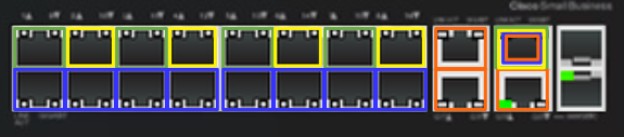
Since I have 3 (and soon 4) servers, I’m going to divide up the ports in a visual way; in groups of 4: top left (green) is the host network on vlan10, top right (yellow) is the sometimes used vlan20 network, and the bottom left/right (blue) ports in each group will be the vm/instance vlan30 network. These will either have both ports plugged in for a bond/lagg/lacp, or will be only one port plugged in if we’re also using vlan20 (top right).
Now, given that image, we will be adding ports (as they are numbered on the switch) 1, 3, 5, and 7 to vlan10. Ports 2, 4, 6, and 8 will be vlan20, and ports 9-16 will be vlan30. Ports 17/18 (orange) will be the native vlan. Port 18 will be the trunk port to the other router for all vlans, and port 20 is the link to the WAP gateway (also vlan1)
First, we’ll create VLAN10 and add a [router] interface for it:
G300-20#conf t
SG300-20(config)#vlan 10
SG300-20(config)#interface vlan 10
SG300-20(config-if)#?
  bridge               Bridge configuration commands
  do                   execute an EXEC-level command
  dot1x                dot1x protocol
  end                  Exit from configure mode
  exit                 Exit from current context
  help                 Description of the interactive help system
  ip                   Global IP configuration commands
  ipv6                 IPv6 commands
  name                 set vlan name
  no                   Negate command
  service-acl          Apply an ACL to particular interface.
  shutdown             Shutdown the selected interface
  snmp                 SNMP
  sntp                 Global Simple Network Time Protocol (SNTP)
                       configuration subcommands
SG300-20(config-if)#ip address 10.10.10.1 255.255.255.0
SG300-20(config-if)#name oshost
SG300-20(config-if)#exit
SG300-20(config)#
Next, we’ll configure each port (ge1, ge5, ge9, ge13) in the same way, setting the port mode, adding it to the vlan, and enabling portfast:
SG300-20(config)#interface ge1
SG300-20(config-if)#switchport mode ?
  general              generic port mode
  access               vlan unaware port
  trunk                vlan aware port
  customer             customer equipment port
SG300-20(config-if)#switchport mode access
SG300-20(config-if)#switchport access ?
  multicast-tv         multicast transmissions from a vlan
  vlan                 vlan
SG300-20(config-if)#switchport access vlan 10
SG300-20(config-if)#spanning-tree portfast
SG300-20(config-if)#exit
Now for each of those green vlan10 (ge1, ge5, ge9, ge13) ports in the pic, we should see that it is now assigned to vlan10:
SG300-20#show interface switchport ge1
Port : gi1
Port Mode: Access
Gvrp Status: disabled
Ingress Filtering: true
Acceptable Frame Type: admitAll
Ingress UnTagged VLAN ( NATIVE ): 10

Port is member in:

Vlan               Name               Egress rule Port Membership Type
---- -------------------------------- ----------- --------------------
 10                 oshost             Untagged          Static
Finally, let’s add a dhcp pool for this vlan:
SG300-20(config)#ip dhcp pool network oshost
SG300-20(config-dhcp)#address low10.10.10.100 high 10.10.10.150 255.255.255.0
SG300-20(config-dhcp)#
SG300-20(config-dhcp)#default-router 10.10.10.1
SG300-20(config-dhcp)#dns-server 8.8.8.8
SG300-20(config-dhcp)#time-server 129.6.15.29
SG300-20(config-dhcp)#domain-name lab
SG300-20(config-dhcp)#exit
SG300-20(config)#exit
SG300-20#copy run start
Easy peasy right? :-)
VLAN20 – OpenStack Private/Internal Network
Depending on the type of setup we’re running in the lab, we might have split our host/management network into two separate networks: public and internal. This could also be a “dmz” network for floating ip addresses, and other crazy configs.
To create the VLAN20 network, simply follow the instructions above for VLAN10, but use 10.10.20.0/24 with a default gateway/interface of 10.10.20.1 with a corresponding dhcp pool for 10.10.20.100-10.10.20.150.
VLAN30 – OpenStack VM/Instance Network
This network will carry the GRE tunnel traffic from all of the “private” VM instance networks to the Neutron node.
To create the VLAN30 network, simply follow the instructions above for VLAN10, but use 10.10.30.0/24 with a default gateway/interface of 10.10.30.1. Unlike the other networks, do NOT create a dhcp pool for this network. All interfaces connected to it will have no ip address assigned and will all bridge.
VLAN Trunk Port
We’re also going to need a trunk port to carry all vlan traffic between this switch and the SG300-10 we’ll configure later. To do that, we just need to set the mode to trunk, and add the allowed vlans to that port:
SG300-20#conf t
SG300-20(config)#int gi19
SG300-20(config-if)#switchport mode ?
  general              generic port mode
  access               vlan unaware port
  trunk                vlan aware port
  customer             customer equipment port
SG300-20(config-if)#switchport mode trunk
SG300-20(config-if)#switchport trunk ?
  allowed              Specify trunk as allowed
  native               vlan unaware port
SG300-20(config-if)#switchport trunk allowed ?
  vlan                 Configure VLANs in a trunk port
SG300-20(config-if)#switchport trunk allowed vlan ?
  add                  Specify which VLAN to add to the port.
  remove               Specify the VLAN to remove from port.
SG300-20(config-if)#switchport trunk allowed vlan add ?
  <2-4094>             Specify which VLAN to add to the port.
  all                  Specify all existing IEEE 802.1 VLANs.
SG300-20(config-if)#switchport trunk allowed vlan add all
SG300-20(config-if)#exit
SG300-20(config)#exit
Now we should see all vlans listed on the g19 interface:
SG300-20#show interface switchport gi19
Port : gi19
Port Mode: Trunk
Gvrp Status: disabled
Ingress Filtering: true
Acceptable Frame Type: admitAll
Ingress UnTagged VLAN ( NATIVE ): 1

Port is member in:

Vlan               Name               Egress rule Port Membership Type
---- -------------------------------- ----------- --------------------
 1                  1                  Untagged          Static
 10               oshost                Tagged           Static
 20               osdata                Tagged           Static
 30                osvm                 Tagged           Static
Time to test out some things, like dhcp. :-P
Plug In Some Cables
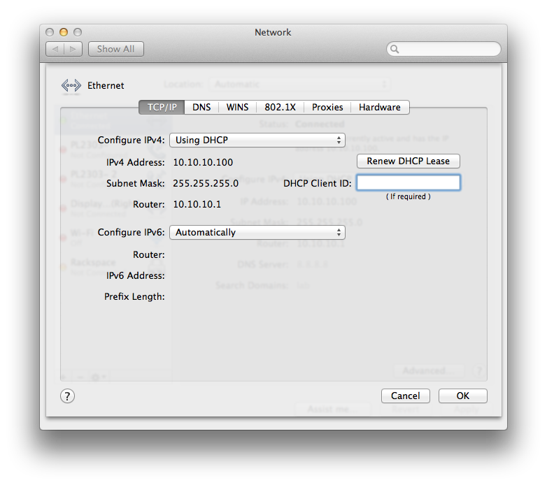
Now, let’s see if this all works. First, let’s connect our ethernet port to port 1 or 2 and see if we get the right DHCP info from vlan1 on the switch:
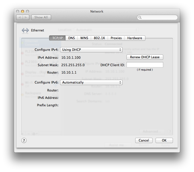
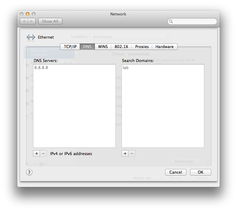
Nice! vlan1 ip and router, dns servers, and default domain name. Now, let’s connect our ethernet port to and of the vlan10 (oshost) ports (2, 4, 6, 8):
Winning! If you’ve created vlan20/30, give those a shot as well. Also, if we now connect to the WAP via wifi, we should also get a 10.10.1.x address from the switches dhcp server on vlan1.
Next Time on This Old Homelab
Next up, we’ll start configuring our SG300-10 switch to trunk the vlans to our workbench (fancy term for desk) from the lab space and start configuring PXE/FOG to get our first OS installed over the network.